Draft Surface from a Curve - Distance
![]()
This function allows users to create drafted surfaces based on a curve. Draft dimensions and angles are user controlled.
This section of the documentation explains the Distance parameters and options related to this function. Angle and Draft reference parameters and options are explained in a separate section.
An additional section explains functionality found under the Advanced tab.
Access
- Click the
 icon in the Surfaces tab, or
 - Type Draft in the Quick Search input field and select from the resulting drop-down list.
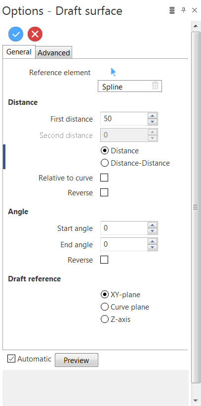
After launching the function, the Draft surface - General tab dialog box is displayed in the left panel and contains the different parameters used to determine how the draft surface is generated.
|
Reference element |
Lists all of the currently selected elements on which the draft function is to be applied. Clicking on the Use the Clicking on the |
 icon allows you to switch back into the element selection mode allowing you to modify your selection by selecting / deselecting elements in the graphic area.
Distance
This section contains parameters and options which determine the distance of the drafted surface.
Default Angle and Draft reference parameters / options are maintained in the following example.
|
Distance |
Activating this option (located below the First distance and Second distance input fields) indicates that a drafted surface is generated on one side of the selected curve. |
|
Distance-Distance |
Activating this option indicates that a drafted surface is generated on both sides of the selected curve. This will also activate the Second distance input field. |
|
Relative to curve |
Activating this option indicates that the draft surface distance is calculated with respect to the selected curve. If not, it is calculated with respect to the default XY plane reference. Refer to the examples below. |
|
Reverse |
Reverses the direction of the drafted surface with respect to the reference curve. |
Procedure
Example Part
The following curve, drawn from the origin of the Absolute workplane, is used in the following examples.

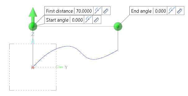
- Activate the Distance option.
- Enter 70 in the First distance field (the Second distance field is not active).
- Select the curve in the graphic area to obtain the following result:
Some dynamic operations are now possible directly in the graphic area (ignoring the Start and End angle options for the moment).
Positioning the cursor over the Z axis direction arrow (which turns it blue) and then pressing and holding down the left mouse button allows you to drag the arrow in an upward or downward direction to adjust the First distance value.
Alternatively, you can modify the value in the numeric input field.
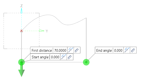
- Click on the Reverse
 icon next to the numeric input field to invert the direction of the drafted surface (this automatically activates the Reverse option in the dialog box).
This gives the following result:
- Activate the Relative to curve option to show the effect on the drafted surface:
- Deactivate the Reverse option and activate the Distance-Distance option to obtain the following result:
- Either drag the green sphere (which turns blue when the cursor is positioned over it) in a downward direction until the required value is displayed in the numeric input field, or
- Enter the required value in the input field in the graphic area or in the dialog box itself.

![]() Note:
Note:
You can move the dynamic input fields in the graphic area by pressing and holding down the left mouse button after positioning the cursor over the text box (e.g. First distance) then dragging it to a new position. This was done in the above screen shot for greater visibility of the relative to curve drafted surface.
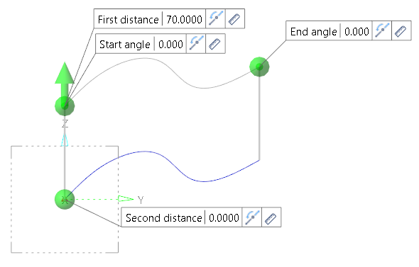
The new Second distance input field is now displayed in the graphic area.

![]() Note:
Note:
When dragging the sphere in a downwards direction, the value is negative.
See also...
Draft Surface from a Curve - Angle and Draft Reference
Draft Surface from a Curve - Advanced Tab